A baseline building is not used when COMNET is used for Design to Earn ENERGY STAR.
The HVAC system in the baseline building depends on the primary building activity, the size of the building and the energy source used for heating in the proposed design. [bookref id="hvac-mapping"] shows the HVAC system types that apply in each case. Details about these systems are provided in subsequent sections.
Many of the building descriptors have a one-to-one relationship between the proposed design and the baseline building, for example, every wall in the proposed design has a corresponding wall in the baseline building. For HVAC systems, this one-to-one relationship generally does not hold. The HVAC system serving the proposed design and the baseline building may be completely different, each with different components, etc.
[figure title="HVAC Mapping" id="hvac-mapping"]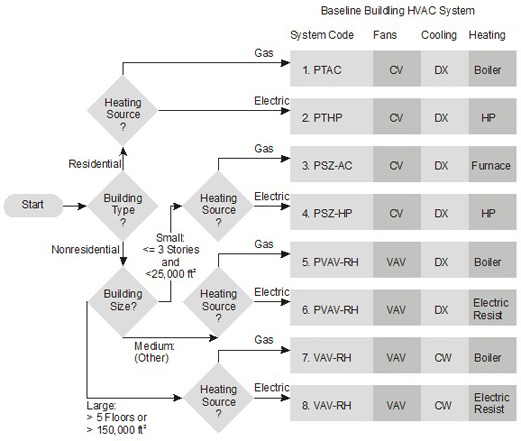 [/figure]
For systems 1 through 4, each thermal block shall be served by a separate system. For systems 5 through 8, a single system serves the whole building with a separate air handler for each floor. Systems 5 and 6 are packaged equipment with DX cooling and fans combined in the same box. For these systems, each floor will have its own system.
There are several important exceptions to the HVAC mapping rules that apply to spaces with unusual internal heat gains, different schedules, special pressurization requirements, or unique outside air needs. These exceptions will typically apply to laboratories, data centers, and many spaces in healthcare facilities. See Chapter 7 for the special requirements for these building types. The exceptions are described below:
- Separate occupancies in mixed use buildings are served by separate baseline building systems. Examples include residential spaces located over retail and other similar conditions. (See the PRM, G3.1.1, Exception a.)
- A separate baseline building system shall serve laboratories or group of laboratories with an exhaust system designed for 5,000 cfm or more of air movement. The baseline building system serving the laboratory spaces shall be either system 5 (PVAV with hot water reheat) or system 6 (PVAV with parallel fan-powered boxes and electric reheat), depending on the heating source in the building. The PVAV system must be capable of reducing the exhaust and makeup air volume to 50% of design values during unoccupied periods. This exception essentially requires VAV for both the supply fan and the exhaust system. (See the PRM, G3.1.1, Exception c.)
- Spaces that do not trigger the laboratory exception above may still have a separate baseline building system. Either system 3 (PSZ-AC) or system 4 (PSZ-HP) shall serve spaces in the baseline building (depending on the heating source for the building) when one of the following conditions apply:
- Spaces on a floor have significantly different schedules or internal heat loads. Heat gain differences of more than 10 Btu/h or operation schedule differences of more than 40 hours/week trigger this exception. (See the PRM, G3.1.1, Exception b.)
- Spaces on a floor have "special pressurization relationships, cross-contamination requirements, or code-required minimum circulation rates". Many laboratory spaces with fume hoods would likely trigger this exception. (See the PRM, G3.1.1, Exception c.)
These special systems serve just the spaces that trigger the exceptions. The rest of the building/floor is served by the baseline building HVAC system and air handlers shown in [bookref id="hvac-mapping"].
The HVAC system in the baseline building depends on the primary building activity, the size of the building and the energy source used for heating in the proposed design. [bookref id="hvac-mapping"] shows the HVAC system types that apply in each case. Details about these systems are provided in subsequent sections.
Many of the building descriptors have a one-to-one relationship between the proposed design and the baseline building, for example, every wall in the proposed design has a corresponding wall in the baseline building. For HVAC systems, this one-to-one relationship generally does not hold. The HVAC system serving the proposed design and the baseline building may be completely different, each with different components, etc.
[figure title="HVAC Mapping" id="hvac-mapping"][/figure]
For systems 1 through 4, each thermal block shall be served by a separate system. For systems 5 through 8, a single system serves the whole building with a separate air handler for each floor. Systems 5 and 6 are packaged equipment with DX cooling and fans combined in the same box. For these systems, each floor will have its own system.
There are several important exceptions to the HVAC mapping rules that apply to spaces with unusual internal heat gains, different schedules, special pressurization requirements, or unique outside air needs. These exceptions will typically apply to laboratories, data centers, and many spaces in healthcare facilities. See Chapter 7 for the special requirements for these building types. The exceptions are described below:
- Separate occupancies in mixed use buildings are served by separate baseline building systems. Examples include residential spaces located over retail and other similar conditions. (See the PRM, G3.1.1, Exception a.)
- A separate baseline building system shall serve laboratories or group of laboratories with an exhaust system designed for 5,000 cfm or more of air movement. The baseline building system serving the laboratory spaces shall be either system 5 (PVAV with hot water reheat) or system 6 (PVAV with parallel fan-powered boxes and electric reheat), depending on the heating source in the building. The PVAV system must be capable of reducing the exhaust and makeup air volume to 50% of design values during unoccupied periods. This exception essentially requires VAV for both the supply fan and the exhaust system. (See the PRM, G3.1.1, Exception c.)
- Spaces that do not trigger the laboratory exception above may still have a separate baseline building system. Either system 3 (PSZ-AC) or system 4 (PSZ-HP) shall serve spaces in the baseline building (depending on the heating source for the building) when one of the following conditions apply:
- Spaces on a floor have significantly different schedules or internal heat loads. Heat gain differences of more than 10 Btu/h or operation schedule differences of more than 40 hours/week trigger this exception. (See the PRM, G3.1.1, Exception b.)
- Spaces on a floor have "special pressurization relationships, cross-contamination requirements, or code-required minimum circulation rates". Many laboratory spaces with fume hoods would likely trigger this exception. (See the PRM, G3.1.1, Exception c.)
These special systems serve just the spaces that trigger the exceptions. The rest of the building/floor is served by the baseline building HVAC system and air handlers shown in [bookref id="hvac-mapping"].
The HVAC system in the baseline building depends on the primary building activity, the size of the building and the energy source used for heating in the proposed design. Figure 6.1.2-1 shows the HVAC system types that apply in each case. Details about these systems are provided in subsequent sections.
Many of the building descriptors have a one-to-one relationship between the proposed design and the baseline building, for example, every wall in the proposed design has a corresponding wall in the baseline building. For HVAC systems, this one-to-one relationship generally does not hold. The HVAC system serving the proposed design and the baseline building may be completely different, each with different components, etc.
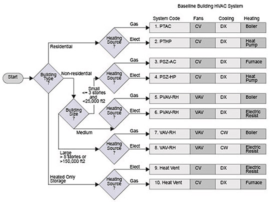
For systems 1 through 4 and 9 and 10, each thermal block shall be served by a separate system. For systems 5 through 8, a separate air handler shall serve for each floor. Systems 5 and 6 are packaged equipment with DX cooling and fans combined in the same box. For these systems, each floor will have its own system.
There are several important exceptions to the HVAC mapping rules that apply to spaces with unusual internal heat gains, different schedules, special pressurization requirements, or unique outside air needs.
There are several important exceptions to the HVAC mapping rules that apply to spaces with unusual internal heat gains, different schedules, special pressurization requirements, or unique outside air needs. These special cases are addressed through the exceptions to Section G3.1.1 of the PRM. These address mixed use buildings, spaces in buildings with unusual loads or schedules, laboratories with fume hoods and commercial kitchens. The exceptions are described below:
- Mixed residential and nonresidential buildings. If a building has both residential and nonresidential spaces with their total conditioned floor area greater than 20,000 ft², such as a residential tower with retail and restaurants at the base, then the HVAC system type is determined separately for the residential and nonresidential portions.
- Special spaces in buildings. Examples are computer rooms or guard stations. In these cases, the baseline building system for the special space is system type 3 or 4, depending on the heating source for the main building. This exception applies when a space has significantly different operating conditions or thermal loads. The threshold for internal loads is a difference of more than 10 Btu/h-ft². The threshold weekly operating hours is when the difference is more than 40 hours.
- Laboratories. For laboratory spaces with a minimum exhaust of 5,000 cfm, the HVAC system type should be 5 or 7 (depending on heating source) serving only the laboratory spaces. For all electric buildings, the heating is electric resistance.
- Kitchens. Baseline building systems that serve kitchens with an exhaust hood airflow rate greater than 5,000 cfm shall use either baseline building system 5 or 7. System 5 is a packaged VAV and 7 is a VAV with a chilled water plant. System 7 would be used if the baseline building has a chilled water plant, otherwise system 5 would be used. The baseline building shall have a demand ventilation system that operates on at least 75% of the exhaust air. The system shall reduce exhaust and replacement airflow rates by 50% for one half of the kitchen's occupied hours. If the proposed design uses demand ventilation, the same airflow schedule shall be used.
- Heated only spaces. A heating and ventilating system (with no cooling) shall be used for heated only storage, stairwells, vestibules, electrical/mechanical rooms and restrooms not exhausting or transferring air from mechanically cooled thermal zones (systems 9 or 10). When unheated storage or other qualifying spaces exist in a building, the remaining spaces are modeled as heated and cooled and follow the system map in Figure 6.1.2-1. The floor area to be used in determining the baseline building system types should exclude the heated only spaces.
When the rated building used purchased heating (hot water or steam) and/or purchased chilled water, the HVAC system mapping is modified as follows:
- Purchased heat, but not purchased chilled water. The purchased heat is assumed to be produced by fossil fuels, and the mappings in Figure 6.2.1-1 apply with purchased heat substituted as the heating source.
- Purchased chilled water, but not purchased heat. The mappings in Figure 6.2.1-1 apply with the following modifications:
- Purchased chilled water is substituted for the cooling source.
- Systems 1 and 2 are constant volume fan coil units with fossil fuel boilers.
- Systems 3 and 4 are constant volume single zone air handlers with fossil fuel furnaces.
- System 7 is used in place of System 5.
- System 8 is used in place of System 6.
- Both purchased chilled water and heat. The purchased heat is assumed to be produced by fossil fuels and the mappings in Figure 6.2.1-1 apply with the following modifications:
- Purchased heat and purchased chilled water is substituted for the heating and cooling sources.
- System 1 is constant volume fan coil units.
- System 3 is constant volume single zone air handlers.
- System 7 is used in place of System 5.
The HVAC system in the baseline building depends on the building type, the size of the building and the climate zone. The baseline HVAC system type for each building type and size is shown in Table 3.1-1. Table 3.1-2 shows the baseline HVAC system type for special space types. Details about these baseline building systems are provided in Table 3.1-3 and subsequent sections of the MGP.
Table 3.1-1 – HVAC System Mapping for Building Types
|
|
|
|
Baseline Building System Type |
|
|
Building Type |
Description/Qualifiers |
Size |
Cold Climates (3b, 3c, and 4-8) |
Warm Climates (1a, 2a, and 3a) |
|
Residential |
Dormitories, hotels, motels, and multifamily buildings of four or more stories. |
Any size |
1 PTAC |
2 PTHP |
|
Public Assembly |
Houses of worship, auditoriums, movie theaters, performance theaters, concert halls, arenas, enclosed stadiums, ice rinks, gymnasiums, convention centers, exhibition centers, and natatoriums. |
< 120,000 ft² |
3 PSZ-AC |
4 PSZ-HP |
|
≥ 120,000 ft² |
12 SZ-CV-HW |
13 SZ-CV-ER |
||
|
Retail |
|
Low rise |
3 PSZ-AC |
4 PSZ-HP |
|
Other than |
Use “Other Nonresidential” |
|||
|
Hospitals |
|
Other than large |
5 PVAV Reheat |
5 PVAV Reheat |
|
Large, e.g. |
7 VAV Reheat |
7 VAV Reheat |
||
|
Other Nonresidential |
Buildings that are not public assembly, hospitals or low rise retail |
Small, e.g. |
3 PSZ-AC |
4 PSZ-HP |
|
Medium, e.g. buildings that are not small or large |
5 PVAV Reheat |
6 PVAV PFP boxes |
||
|
Large, e.g. |
7 VAV Reheat |
8 VAV PFP boxes |
||
Certain special spaces within buildings shall have their own separate HVAC systems as shown in Table 3.1.2-2
Table 3.1-2 – HVAC System Mapping for Special Space Types
|
|
|
|
Baseline Building System Type |
|
|
Building Type |
Description/Qualifiers |
Size |
Cold Climates (3b, 3c, and 4-8) |
Warm Climates (1a, 2a, and 3a) |
|
Residential |
Guest rooms, living quarters, private living space, and sleeping quarters. |
Any size |
1 PTAC |
2 PTHP |
|
Heated Only |
Spaces with heating only systems in the proposed design, serving storage rooms, stairwells, vestibules, electrical/mechanical rooms, and restrooms not exhausting or transferring air from mechanically cooled thermal zones. |
Any size |
9 HV Furnace |
10 HV Electric |
|
Laboratories |
Total laboratory exhaust rate greater than 15,000 cfm. |
Located in large nonresidential buildings or hospitals |
5 PVAV Reheat |
5 PVAV Reheat |
|
Located in other buildings |
7 VAV Reheat |
7 VAV Reheat |
||
|
Computer Rooms |
> 3,000,000 Btu/h or >600,000 Btu/h where the baseline building system is 7 or 8 |
Any size |
11 SZ-VAV |
11 SZ-VAV |
Table 3.1-3 – Baseline Building HVAC System Descriptions
|
System No. |
System Type |
Fan Control |
Cooling Type |
Heating Type |
|
1. PTAC |
Packaged terminal air conditioner |
Constant volume |
Direct expansion |
Hot-water fossil fuel boiler |
|
2. PTHP |
Packaged terminal heat pump |
Constant volume |
Direct expansion |
Electric heat pump |
|
3. PSZ-AC |
Packaged rooftop air conditioner |
Constant volume |
Direct expansion |
Fossil fuel furnace |
|
4. PSZ-HP |
Packaged rooftop heat pump |
Constant volume |
Direct expansion |
Electric heat pump |
|
5. Packaged VAV with Reheat |
Packaged rooftop VAV with reheat |
Variable air volume |
Direct expansion |
Hot-water fossil fuel boiler |
|
6. Packaged VAV with PFP Boxes |
Packaged rooftop VAV with parallel fan power boxes and reheat |
Variable air volume |
Direct expansion |
Electric resistance |
|
7. VAV with Reheat |
VAV with reheat |
Variable air volume |
Chilled water |
Hot-water fossil fuel boiler |
|
8. VAV with PFP Boxes |
VAV with parallel fan-powered boxes and reheat |
Variable air volume |
Chilled water |
Electric resistance |
|
9. Heating and Ventilation |
Warm air furnace, gas fired |
Constant volume |
None |
Fossil fuel furnace |
|
10. Heating and Ventilation |
Warm air furnace, electric |
Constant volume |
None |
Electric resistance |
|
11. SZ–VAV |
Single-zone VAV |
Variable air volume |
Chilled water |
See note |
|
12. SZ-CV-HW |
Single zone with hot water heat |
Constant volume |
Chilled water |
Hot-water fossil fuel boiler |
|
13. SZ-CV-ER |
Single zone with electric resistance heat |
Constant volume |
Chilled water |
Electric resistance |
|
Notes: 1. For purchased chilled water and purchased heat, see G3.1.1.3. 2. Where the proposed design heating source is electric or other, the heating type shall be electric resistance. Where the proposed design heating source is fossil fuel, fossil/electric hybrid, or purchased heat, the heating type shall be hot-water fossil fuel boiler. |
||||
Most building descriptors have a one-to-one relationship between the proposed design and the baseline building, for example, every wall in the proposed design has a corresponding wall in the baseline building. For HVAC systems, this one-to-one relationship generally does not hold. The HVAC system serving the proposed design and the baseline building may be completely different, each with different components, heating source, etc.
For systems 1 through 4 and 9 through 13, each thermal block shall be served by a separate system. For systems 5 through 8, a separate air handler shall serve for each floor.
Special Cases
There are several important exceptions to the HVAC mapping rules that apply to spaces with unusual internal heat gains, different schedules, special pressurization requirements, or unique outside air needs. These special cases are addressed through the exceptions to Section G3.1.1 of the PRM. These address mixed use buildings, spaces in buildings with unusual loads or schedules, and laboratories. The exceptions are described below:
- Mixed use buildings (G3.1.1b). If a building has a subordinate occupancy with a conditioned floor area of more than 20,000 ft², then the HVAC system type is determined separately for the subordinate occupancy.
- Special spaces in buildings (G3.1.1c). Systems 3 or 4, depending on the climate zone shall be used for spaces that have occupancy, process loads or schedules that differ significantly from the rest of the building. Examples are natatoriums and security stations. This exception does not apply to computer rooms. The threshold for internal loads is a difference of more than 10 Btu/h-ft². The threshold weekly operating hours is when the difference is more than 40 hours.
- Laboratories (G3.1.1d). For laboratory spaces with a total exhaust rate of 15,000 cfm or more, the HVAC system type shall be 5 or 7 (depending on the size of the building within which the laboratory space is located) serving only the laboratory spaces. See Table 3.1.2-2. The lab exhaust fan shall be modeled as constant horsepower reflecting constant-volume stack discharge with outdoor air bypass.
- Heated only spaces (G3.1.1e). Systems 9 or 10 (depending on climate zone) shall be used for spaces in the rated building heating with no cooling system. This applies for heated only storage, stairwells, vestibules, electrical/mechanical rooms and restrooms not exhausting or transferring air from mechanically cooled thermal zones.
- Cooled Spaces in Unheated Building Types (G3.1.1f) If the baseline HVAC system type is 9 or 10, all spaces that are mechanically cooled in the proposed building design shall be assigned to a separate baseline system determined by using the area and climate zone of the mechanically cooled spaces.
- Computer rooms (G3.1.1g). Large computer rooms shall use either HVAC system type 11. The threshold is total computer room peak cooling load of more than 600,000 Btu/h where the baseline HVAC system type is 7 or 8 and a threshold of more than 3,000,000 Btu/h for other baseline building systems. All other computer rooms shall use System 3 or 4.
- Hospitals (G3.1.1h). The baseline system for large hospitals of more than 150,000 ft² or more than 5 stories shall be HVAC system 7. The baseline HVAC system for other hospitals shall be system 5.
Purchased Chilled Water, Hot Water, or Steam
When the rated building uses purchased heating (hot water or steam) and/or purchased chilled water, then the same chilled water, hot water or steam shall also be used in the baseline the HVAC and the HVAC system mapping is modified as shown in Table 3.1.2-4.
Table 3.1.2-4 – Baseline Requirements for Purchased Heat and Purchased Chilled Water Systems
|
Proposed |
Baseline |
||
|
Heating |
Cooling |
Heating Type |
Cooling Type |
|
Purchased Heat |
Chiller or DX |
Purchased Heat |
Based on applicable cooling system from Tables 6.1.2-1 through 6.1.2-3. |
|
Boiler/Electric Resistance or Gas Furnace |
Purchased Chilled Water |
Based on applicable Heating system from Tables 6.1.2-1 through 6.1.2-3.
|
Purchased Chilled Water |
|
Purchased Heat |
Purchased Chilled Water |
Baseline System Type: In accordance to Tables 6.1.2-1 through 6.1.2-3with the following modifications-
|
Baseline System Type: In accordance to Tables 6.1.2-1 through 6.1.2-3with the following modifications- |
A baseline building is not used when COMNET is used for Building EQ.
A baseline building is not used when COMNET is used for Design to Earn ENERGY STAR.